Good News
“We are so pleased that the team is working well together, and I am proud of what we have accomplished. A hydrostatic full sized AOT test with a development partner’s oil is our next big milestone. I am confident that will be right around the corner.”
Cecil Bond Kyte – CEO
Good News
One of the key parameters for successful deployment is the resistivity of the oil. It governs the current draw for a given field strength and ultimately drives the plate spacing of the grid pack. Based on our laboratory data set we have optimized the grid spacing to increase the residence time compared to the last grid pack. Our field strength remains well above the tested minimum, but the additional space will allow for some additional room to implement other design improvements based on recent testing of the full size AOT.
Results
Since reporting on our findings on December 10th, 2021, we have been working to confirm the remaining 20% of design criteria to address the issues identified during our component testing.
Numerous results that have been recorded in the past year have been distilled into several design considerations. Some of the results were confirmation of prior years’ reliability updates and are not included below. The design considerations based on the last year’s results are as follows:
- Round the edges of all metal surfaces.
- Eliminate perpendicular surface of insulators.
- Ensure the gaps between adjacent grid plates are uniform.
- Ensure there can be no interference from mating parts when making any connections but most especially electrical connections.
- Change grid plate’s shape eliminating all corners and fully insulate the perimeter of the grid plate.
- Find new insulating material for supports and spacers.
- Change blind mechanical and electrical designs to be less sensitive to physical changes in insulation.
Design considerations 6 and 7 have been the focus of much of our recent work. We have discovered one of the insulation materials is susceptible to swelling when exposed to crude oil. This swelling is likely the cause of the delamination shown in Figure 2 and Figure 3 of the company’s October 6th, 2021 update and reproduced here in Figure 1.
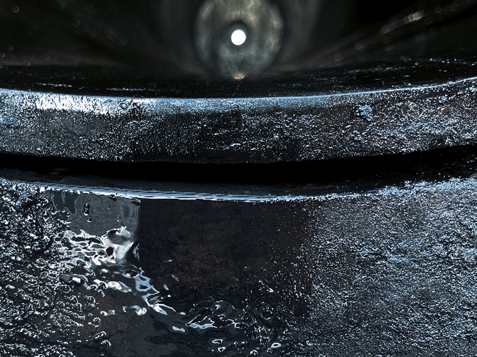
Figure 1: Delamination of resin
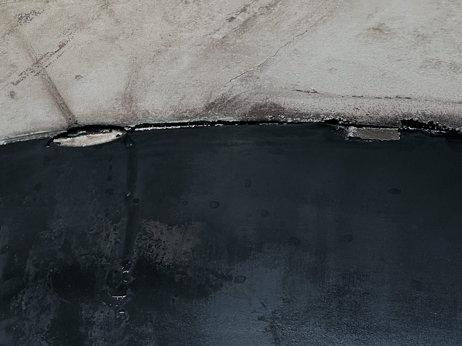
Figure 2: Greatest swelling due to the aromatic fraction
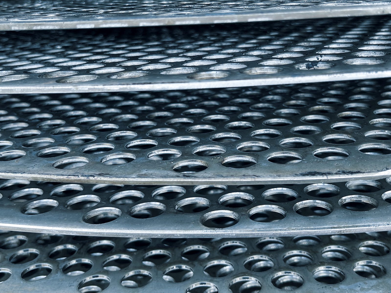
Figure 3: Irregular grid spacing
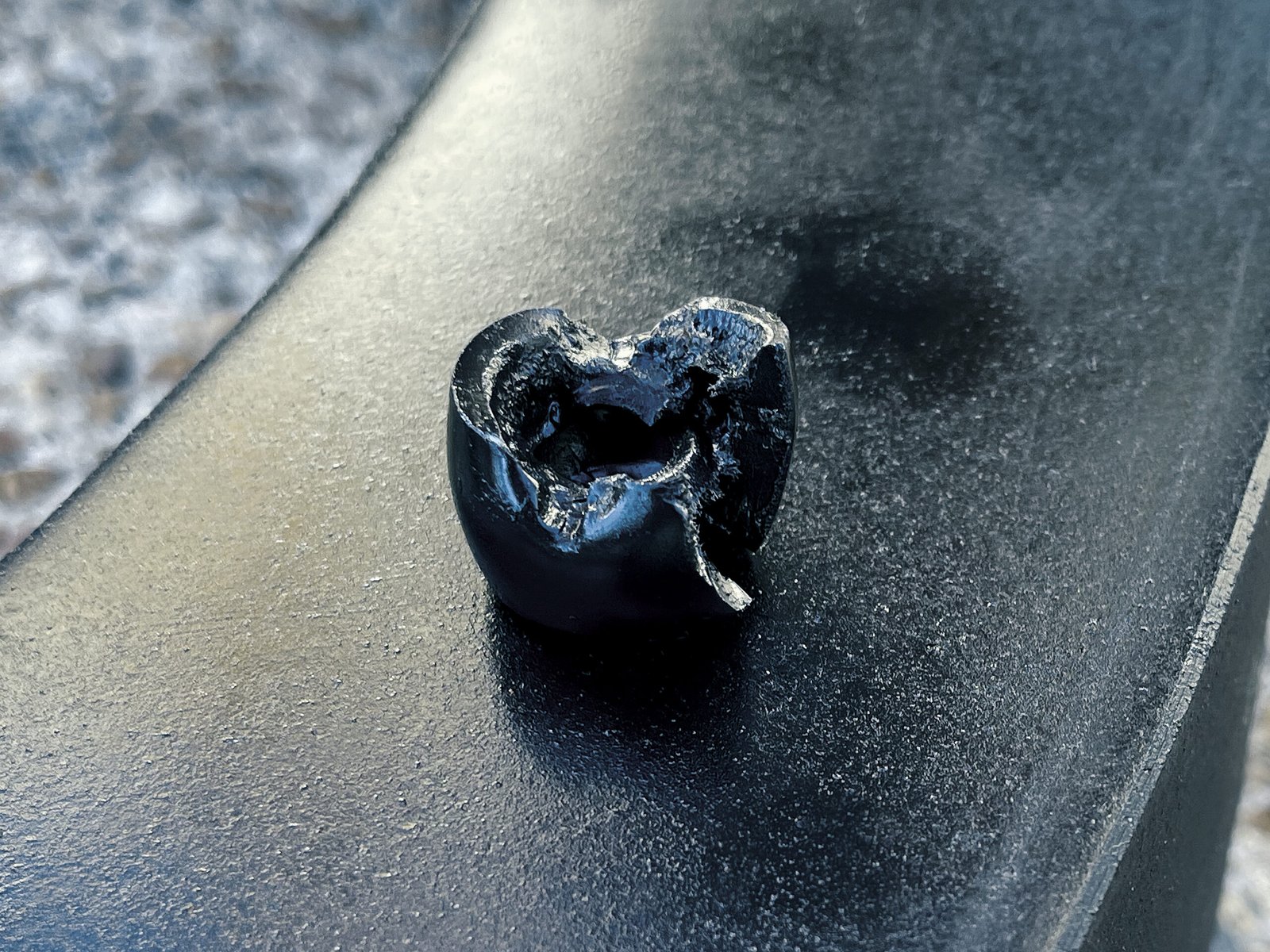
Figure 4: Collapsed space
New Insulation Material
Neither our vendors nor the manufacturers of the resins had crude oil immersion test data, therefore could not suggest alternatives for consideration. The manufacturer believed the material in the original build should have given the best performance. Since no immersion test data was available, we conducted immersion testing of our own to collect baseline data. We tested crude oil, an aliphatic fraction, and an aromatic fraction. We found the aromatic fraction of the oil is the fraction likely causing the swelling. Figure 2 shows coupons 4 and 5 which were exposed to oil, 9 and 10 which were exposed to mineral oil, and lastly 14 and 15 which were exposed to aromatics. The crude oil showed a 10% change in mass and volume in about 30 days and would likely to have continued to slowly increase.
The aromatics showed over an 80% change in one day and plateaued at about 100% change in about a week. Based on this observation we were able to create an accelerated testing protocol. This new testing protocol was effective. Exposure testing is a function of time, and data is still being collected. However, we are confident we have identified three possible alternative materials that show 90% to 98% improvement based on retail samples of the material. Of the three, we have selected a final material for application in hydrostatic testing.
We believe swelling of the insulation material likely led to the electrical failure of the blinds over time. All three blinds in inventory exhibit the same issue shown in Figure 1 highlighted by the red arrow. We will also change the mechanical and electrical connection designs contained in the insulating material to make it less susceptible to being affected should any movement occur with a new material.
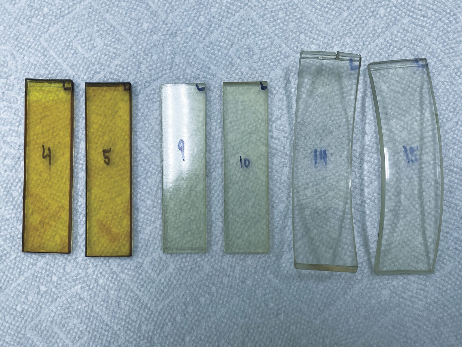
Figure 4: Collapsed space
New Internal Design
Material swelling likely led to the separation of the vessel liner shown in Figure 1 and contributed to poor grid spacing and collapsed grid spacers shown in Figure 3.
We have shared our component testing data, AOT testing data, and lab data with our engineering firm. We have also provided them with our design criteria for review and comment. We completed the conceptual design review of the shared information and have received key component drawings. We are currently working on refining details and final assembly drawings. The new design will be less susceptible to failure resulting in changes in volume of the grid pack insulators so if swelling does occur it will be less likely to contribute to the problems we have encountered to date.
We continue to have discussions with our original development partner. We have shared our conceptual designs with them and will meet with them once again when we have a final design to share. Our developing plan will conclude in the next few weeks with manufacturing of prototype parts, fit testing, and electrical testing culminating in a final hydrostatic test in May.
Based on our preliminary meeting with our original development partner in February, we will be provided oil for component testing as well as a full sized AOT field test.
“Our resolution of the final 20% of design criteria allows us to proceed with finalizing drawings and ordering full sized prototype parts. From there we will rebuild the AOT internals and the blind in preparation of a hydrostatic test.”
Christopher Gallagher, Ph.D – SVP Product Commercialization and Business Development
Notable Accomplishments
- We raised sufficient capital to restart operations.
- Eliminate perpendicular surface of insulators.
- We conducted a successful tear down and component testing program.
- When controlling issues identified in component testing, we were able to demonstrate that we could achieve full voltage without arcing.
- We were able to achieve the highest voltage with the AOT to date whilst controlling many of the issues identified in component testing (a new design is required to control all issues).
- We identified an unknown issue with our insulation leading to a design change that lessens the impact and are well on our way to sourcing a new material that should show 90% improvement.
Safe Harbor Statement
Some of the statements in this release may constitute forward-looking statements under federal securities laws. Please click here for our complete cautionary forward-looking statement.
About Applied Oil Technology
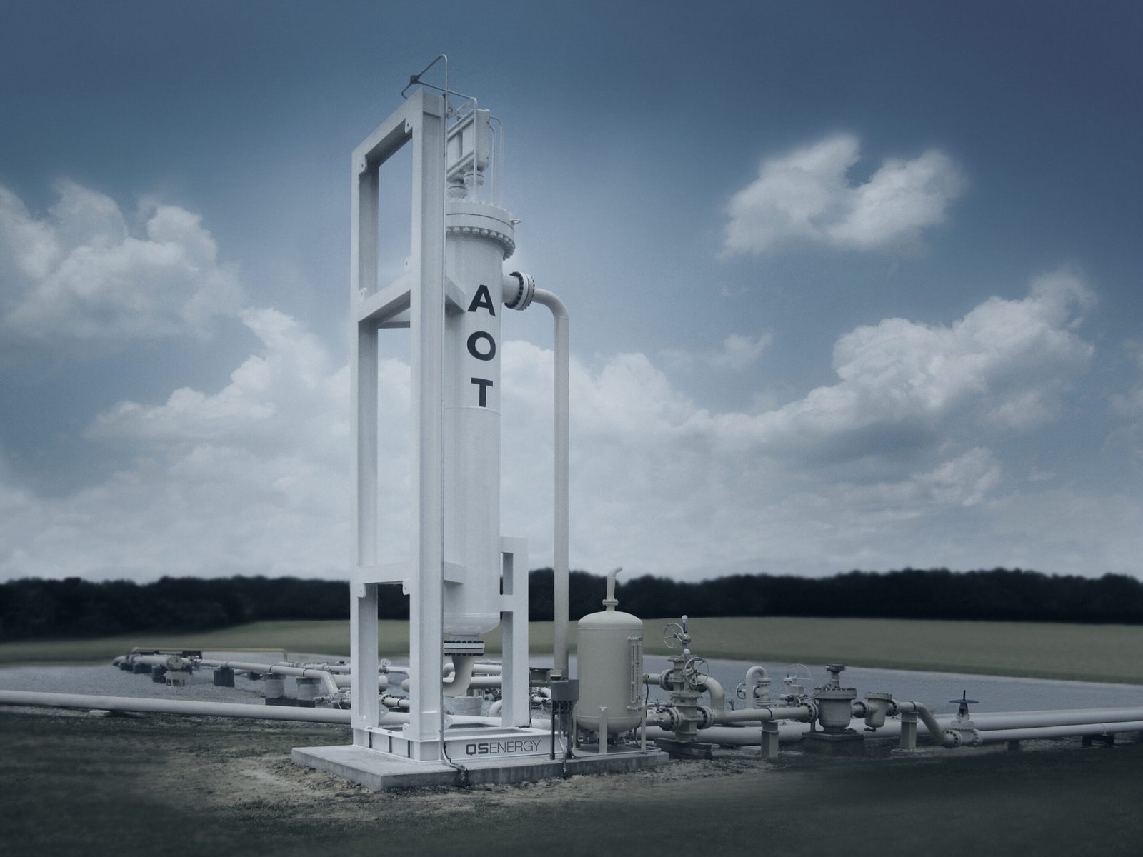
QS Energy’s patented Applied Oil Technology (AOT) is a solid-state turn-key system which uses a high volt / low amp electric field to reduce crude oil viscosity. AOT installs inline on crude oil pipelines, operates unattended without interrupting pipeline flow, with full remote monitoring and control. More information is available online here.
About QS Energy
QS Energy, Inc. (OTCQB: QSEP), develops and markets crude oil flow assurance technologies designed to deliver measurable performance improvements to pipeline operations in the midstream and upstream crude oil markets. More information is available here.


